
Wave Solder Machine
Dual
Wave
SAC305
Alloy

Precision through-hole assembly for connectors, transformers, high-power components, and legacy designs. Wave and selective soldering with full lead-free SAC305 process capability.
From component preparation through final touch-up, each DIP board follows a controlled sequence with defined accept/reject gates at every inspection point.

All through-hole components are kitted, verified against the BOM, and pre-formed if required. Axial and radial lead-forming fixtures ensure consistent standoff height and lead length. Components with long storage intervals undergo solderability testing before kitting. Polarity-sensitive parts are visually double-checked at insertion.
Three insertion methods deployed based on component type, volume, and complexity. Manual insertion for low-volume, odd-form, and high-mass components. Semi-automatic insertion with light-guided workstations for mixed batches. Full automatic insertion for high-volume axial and radial components. Every station uses first-article verification before production begins.
Lead-free wave soldering using SAC305 alloy at controlled pot temperature of 245°C to 265°C. Dual-wave configuration: turbulent first wave for penetration into tight geometries, smooth second wave for fillet formation and icicle control. Conveyor speed, preheat profile, and flux deposition are set per board type and verified on a sacrificial first-article board. Selective soldering system available for mixed-technology boards where only specific through-hole joints need processing.
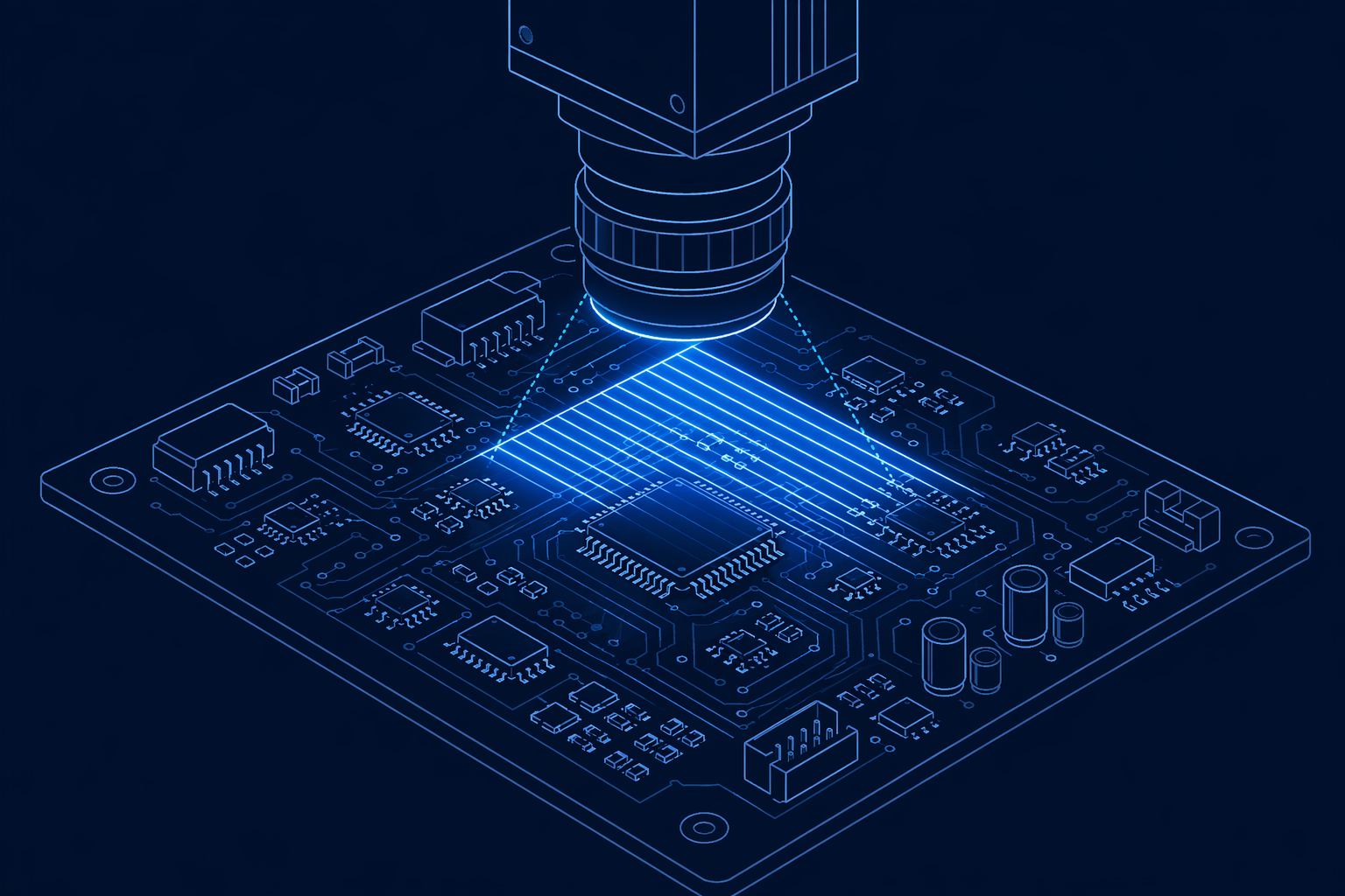
Three-tier inspection protocol. Visual inspection by IPC-A-610-certified operators at 4× magnification covers 100% of solder joints. Automated optical inspection (AOI) supplements visual with programmable defect detection for consistency across production shifts. In-circuit testing (ICT) and functional testing verify electrical continuity and board-level performance against the netlist and test specification.
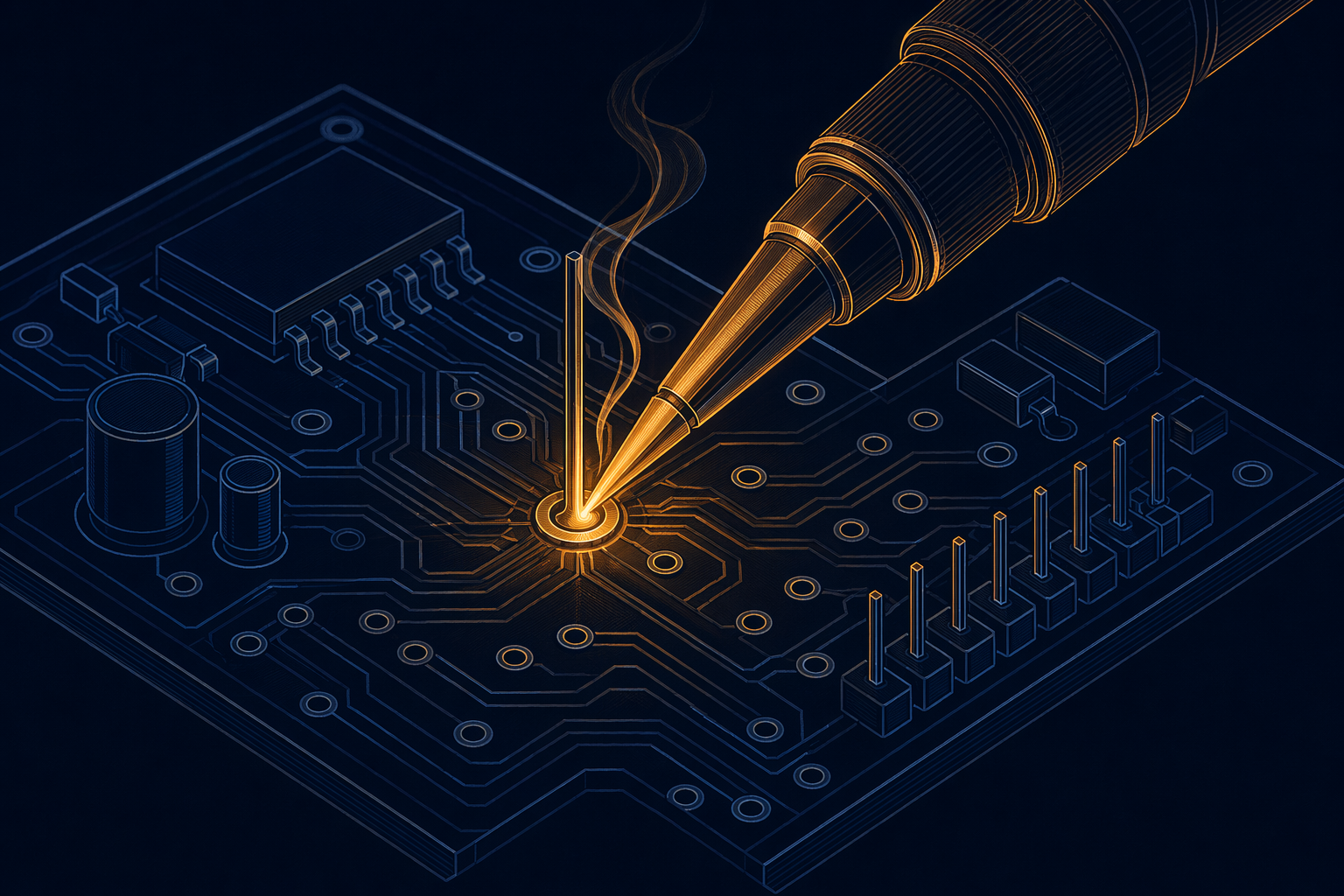
Identified defects are reworked on temperature-controlled soldering stations with ESD-safe tooling. Every reworked joint is re-inspected to the same Class 3 criteria as the original assembly. Rework is tracked per board and per joint in the batch record. Boards exceeding a defined rework count threshold are escalated to engineering review rather than being passed through. Conformal coating is applied after all rework is closed and passed.
Measured specifications for our through-hole assembly line. All values represent production-capable parameters, not theoretical limits.
| Parameter | Specification |
|---|---|
| Max Board Size | 600 mm × 500 mm |
| Board Thickness | 0.8 mm – 6.0 mm |
| Max Component Height | 70 mm |
| Wave Solder Temperature | 245°C – 265°C |
| Insertion Methods | Manual, Semi-Auto, Full Auto |
| Lead-Free Compatible | Yes (SAC305 alloy) |
| Inspection Methods | Visual, ICT, Functional Test |
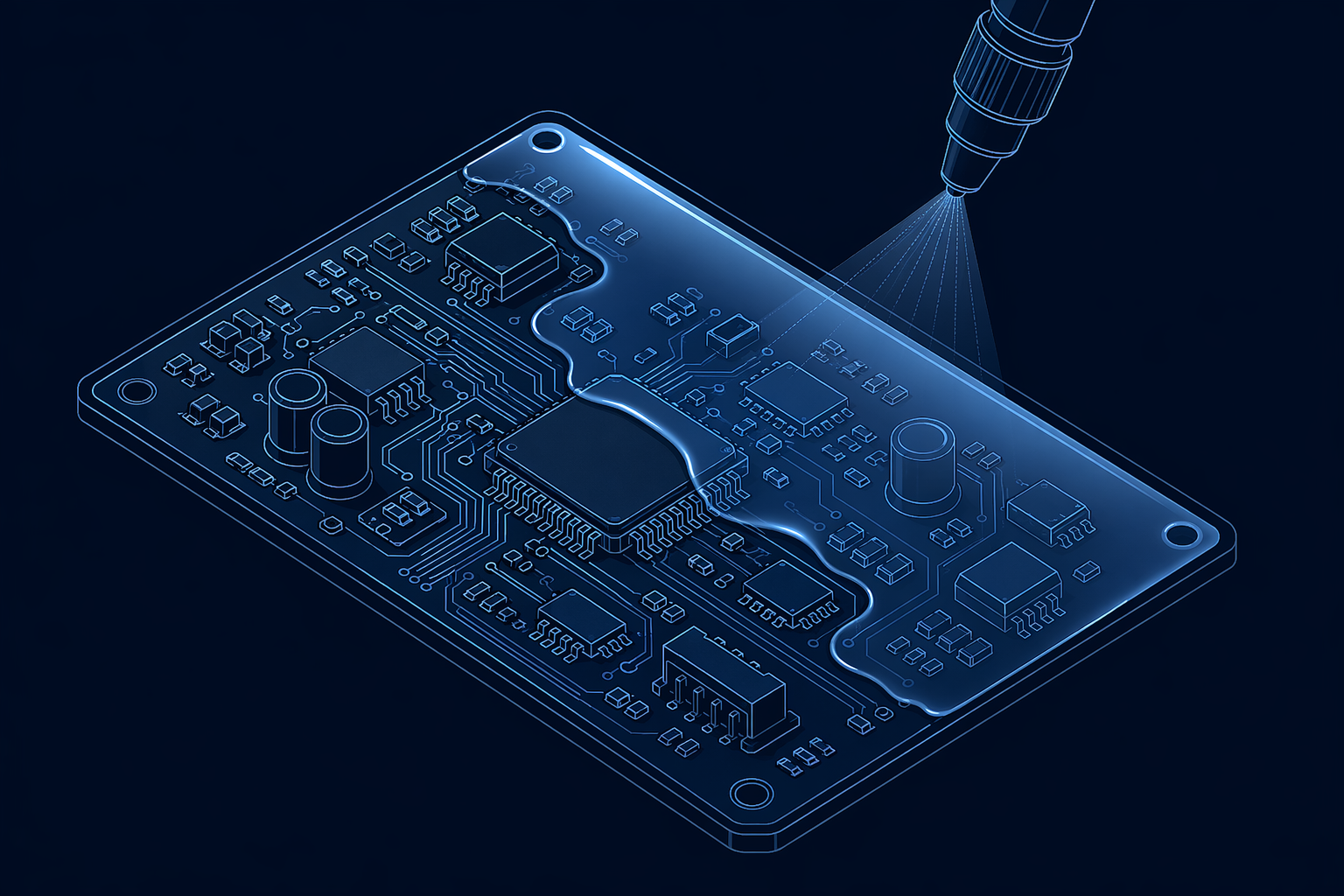
| Conformal Coating | Selective spray + dip |
Through-hole assembly equipment maintained to manufacturer specifications with documented preventive maintenance and calibration schedules.
Our through-hole assembly process is certified, audited, and maintained to the same exacting standards as our SMT line. No double standard, no shortcut for DIP.
Acceptability of Electronic Assemblies — Class 3 criteria applied to every through-hole solder joint. Fill percentage, wetting angle, and fillet geometry are verified against the standard for high-reliability electronic products.
Quality management system covering the full DIP line. Documented procedures for component preparation, wave solder parameter control, inspection workflow, and conformal coating application. Every batch is traceable to its process record.
Requirements for Soldered Electrical and Electronic Assemblies — governing the through-hole soldering process from flux selection to final fillet geometry. Operator training, process control, and inspection all comply with J-STD-001 requirements.
Specify your through-hole requirements, board dimensions, and volume. We return a complete quotation with lead time within one business day.